2026 · RTHM Lab In progress
Projectile Launcher
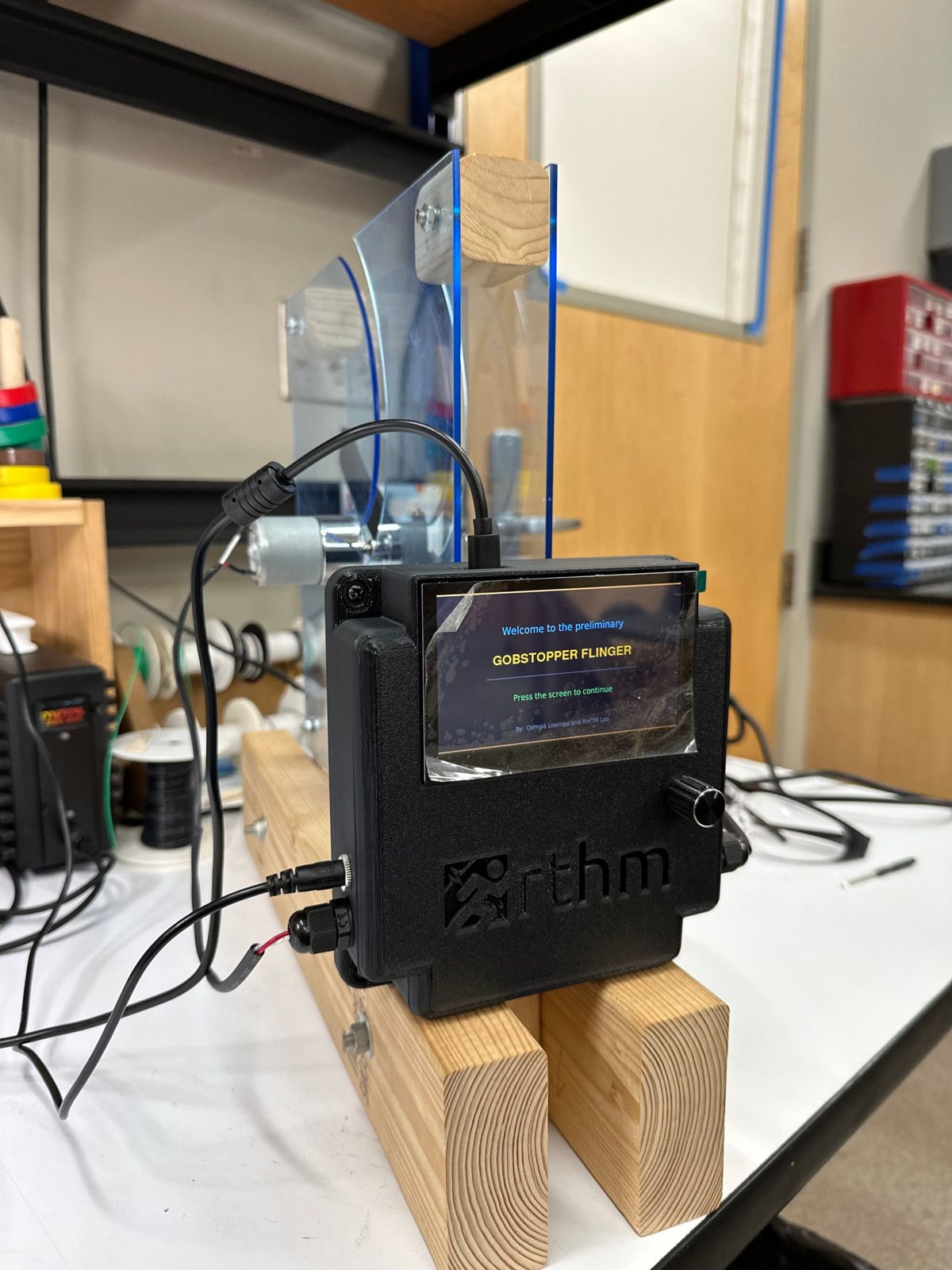
A touchscreen-controlled launcher with closed-loop motor speed control, built in the RTHM Lab as a teaching device for the Dynamics 1 Gobstopper Project.
Why this project
This launcher is being built for the Gobstopper Project in EML 3013 (Dynamics 1). In the project, a motor-driven arm pushes a gobstopper along a curved slot until it flies out as a projectile. Students calculate where it should land, then compare their answer with what the real device does.
The purpose of the device is to show the difference between a real device and analytical calculations. Real hardware has things a textbook model leaves out, such as the motor slowing down under load. This launcher lets students see that difference and measure it.
The radial path
In the project document, the slot that guides the gobstopper is a radial path defined by
r = 8θ (inches)
As the arm spins at angular velocity θ̇, the gobstopper moves outward along this path. At the release point its velocity in polar coordinates is
v = ṙ û_r + r θ̇ û_θ, where ṙ = 8θ̇
From that exit velocity, projectile motion gives the predicted landing point.
What I fixed
When the earlier version of the device was used in class, two things made it hard to compare the calculations with reality:
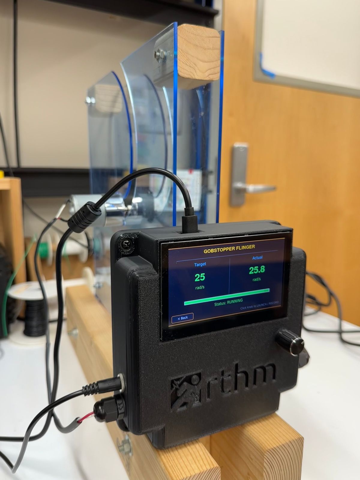
- The arm didn't hold its speed. The motor was commanded to a speed, but it slowed down when the arm hit the gobstopper, and nothing brought it back up. I added closed-loop angular-velocity control, with a startup routine that calibrates the motor and then holds the set speed under load.
- The real speed wasn't known. I added a 12-bit magnetic encoder, read over I2C with threaded sampling, and verified its readings to within 3% using 240 fps video. The touchscreen now shows the target and the measured speed side by side.
While building it, I also tracked down and fixed:
- Logic-level mismatches between components
- An I2C bus conflict
- A control-loop oscillation during startup
What I built
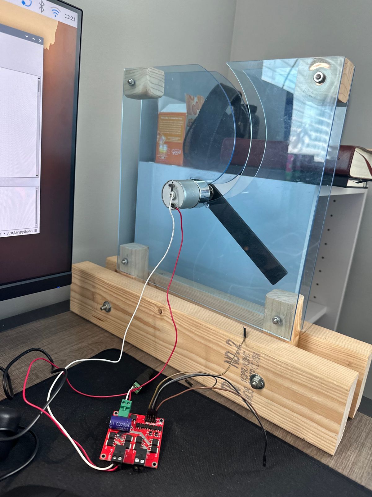
- Hardware: a Raspberry Pi 5, DC motor, H-bridge driver and encoders, housed in a custom 3D-printed enclosure that I designed for the electronics.
- Interface: a multi-screen touchscreen interface written in Python/Pygame, with a knob to launch and record.
How it came together
1. First electronics
2. First controlled motor test
3. Final enclosure
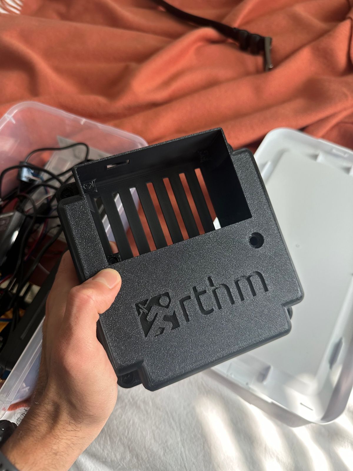
The final casing holds the Raspberry Pi and motor electronics, with a window for the touchscreen, a mount for the control knob, cable ports on the side, and the RTHM Lab logo printed into the face.
Future work
- Infrared (IR) beam sensor: an IR beam will be integrated into the system to detect the gobstopper as it leaves the launcher, so the release can be measured directly and compared with the calculations.