October 2025 Complete
Stirling Engine Design and Machining
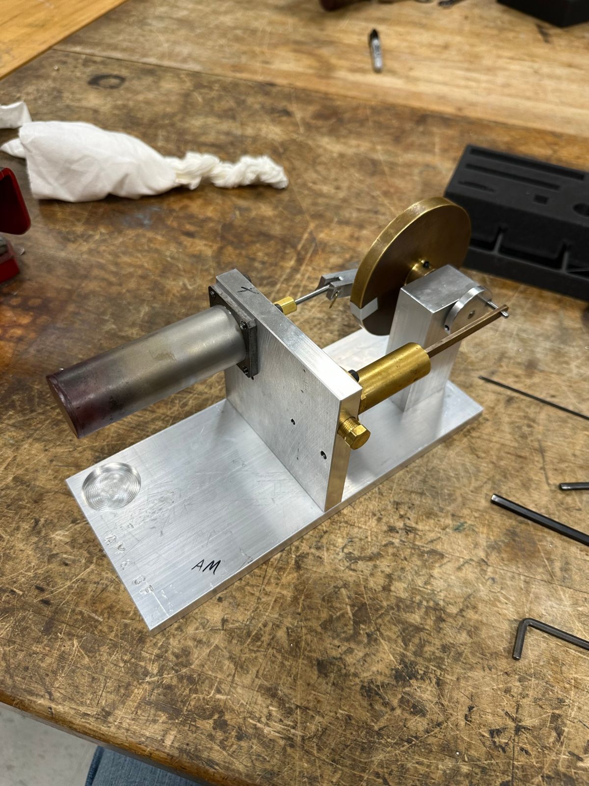
A Stirling engine that I modeled in SOLIDWORKS, documented with drawings for manufacturing, and then machined and assembled in the shop. The finished engine ran at 600 RPM.
Overview
This was a course project where we designed a Stirling engine in SOLIDWORKS and then built it ourselves in the machine shop. The purpose of the project was to give us experience with CAD, reading and composing SOLIDWORKS drawings, machining on the lathe and the mill, and a beginner's introduction to CNC, as well as generally working in a lab.
The machining and assembly part of the project was done together with my classmate, Andrew Miley.
The result: 600 RPM
Once everything was machined and assembled, our engine ran at 600 RPM.
Designing for manufacturing
The biggest focus for me in this project was designing the parts so they could actually be made, and composing the drawings that we would machine from. A model can look right on the screen, but in the shop the drawing is what you go off of, so every dimension and tolerance needs to be there.
- I modeled each component of the engine in SOLIDWORKS, dimensionally accurate to the engineering specification and fit.
- I put all of the components together into the full engine assembly, which let me check the fit and alignment before anything was machined.
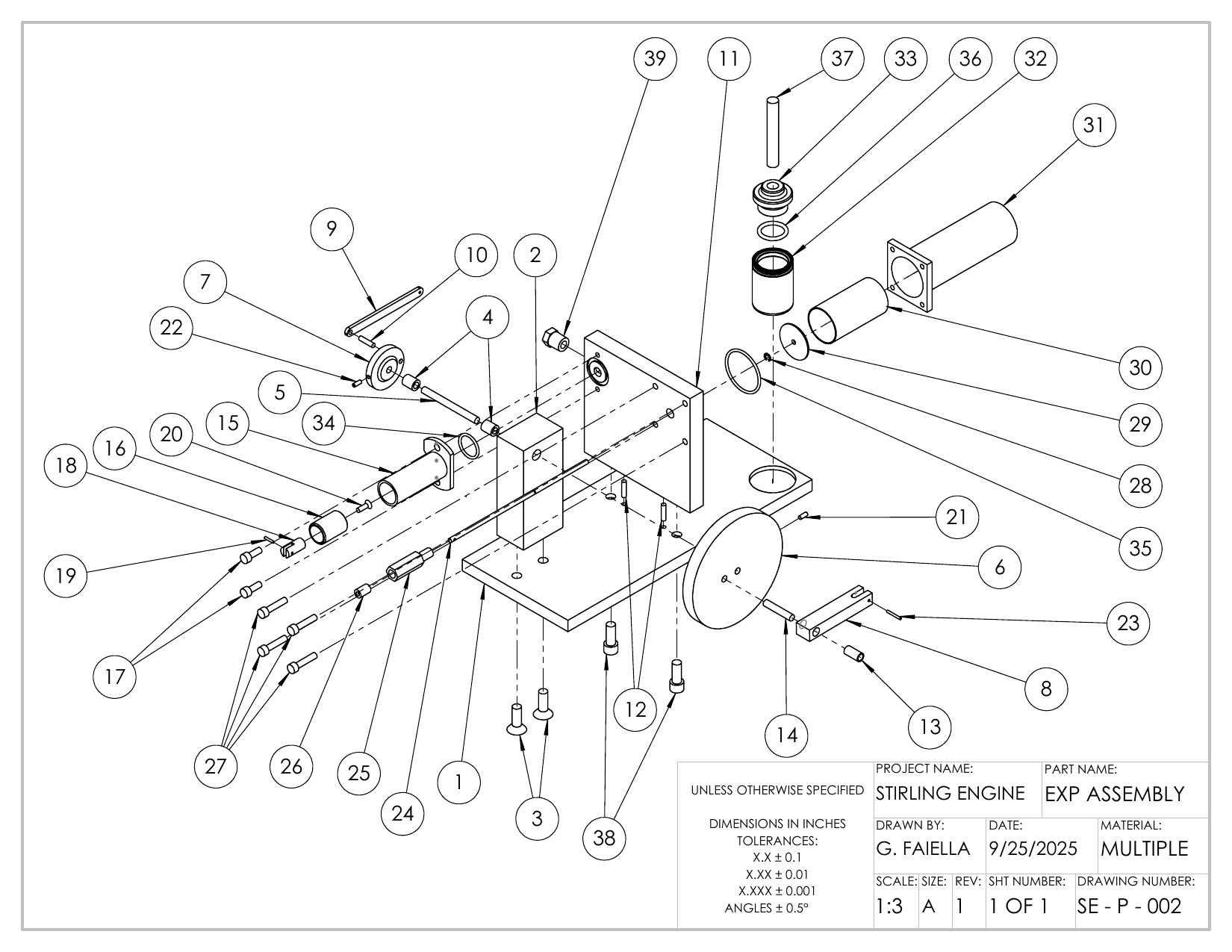
- I composed the drawing package: an assembled view with a section view, an exploded view with numbered balloons, and a bill of materials covering all 39 line items. The drawings are in inches, with tolerances of ±0.1, ±0.01 and ±0.001 depending on the number of decimal places.
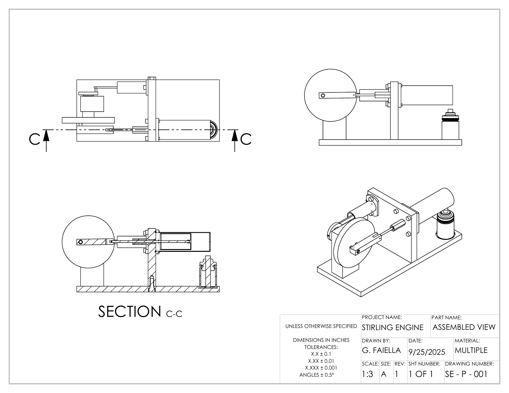
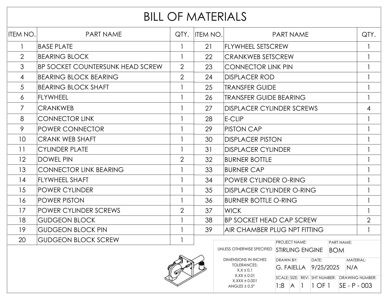
Click a drawing to see it full size, or open the drawing package (PDF).
Exploded view
In the machine shop
Andrew and I machined our parts on the lathe and the mill, and we also got some beginner experience on the CNC. The parts we made were:
- the base plate
- the bearing block
- the cylinder plate, the middle component between the two pistons
- the brass valve on the side of the engine
The screws and bolts were not made by us. After machining, we assembled the engine ourselves.
What I took from it
This project helped me build skills such as machining on the lathe and the mill, and it gave me my first experience with CNC. It also reinforced what I had learned about CAD and drawings in my coursework. Seeing parts made from drawings I composed showed me how important it is to think about manufacturing while designing, not after.